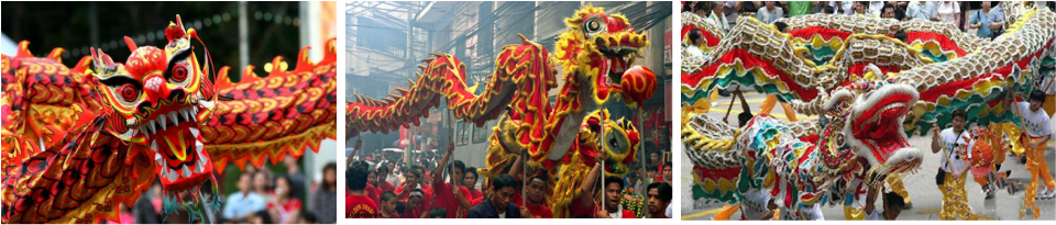
These are some images that served as a reference for the aesthetic I desired to achieve. The main points I took notice of were the bright colors, the intricate designs, and the motion of the floats.
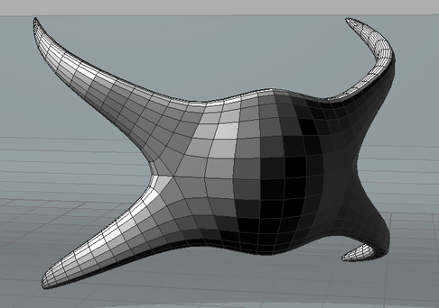
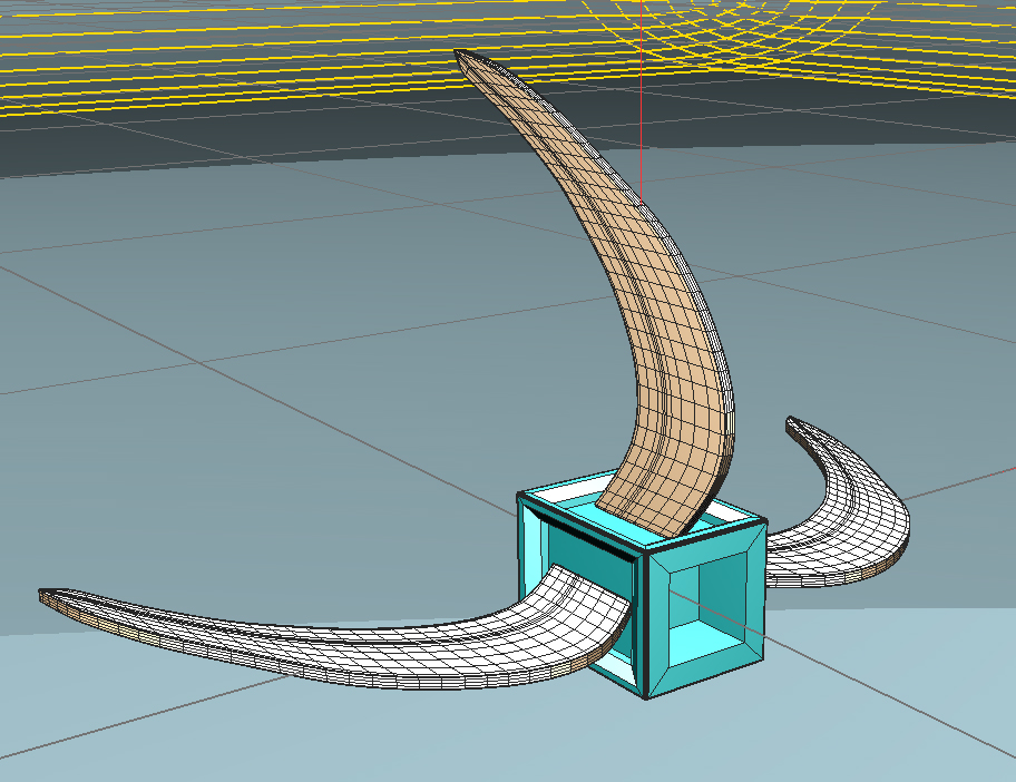
The first thing I modeled was the head of the float. For this model, I took heavy influence from the Dallas Art Fair sculpture.
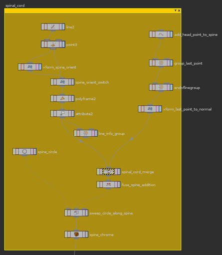
For the spine that holds the sculpture together, I created a line controlled by a sine wave. The line is controlled in a point node that allows for custom user inputs.
ch("../amp") * sin($PT / $NPT * +360 + $FF * ch("../freq"))
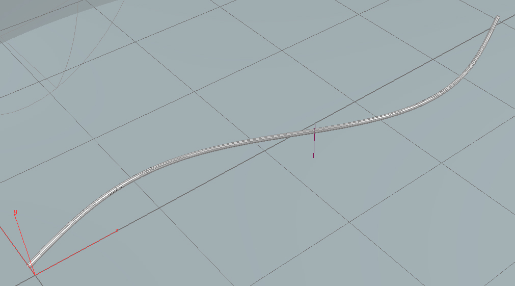
I incorporated a switch node to allow the user to switch between vertical or horizontal motion. This is specified in the user interface by the "Orientation" selection menu. If vertical is chosen, the regular curve is rotated 90 degrees on the Z axis.

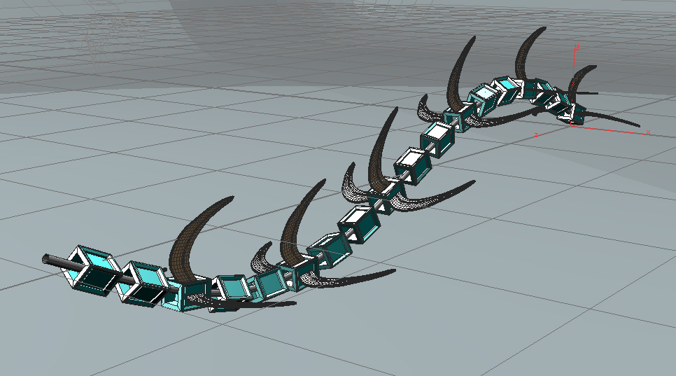
Next, I modeled the vertebrae and winged vertebrae that would be swept along my curve to form the body of my sculpture.
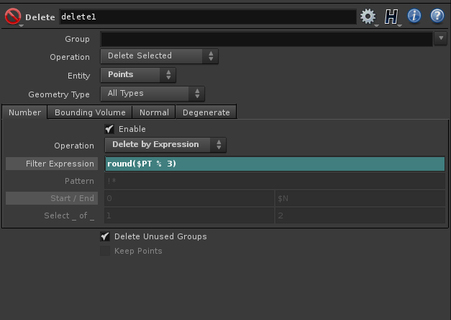
To place the winged vertebrae only on every third point, I used a delete node, deleting all but every third point, to place these vertebrae on. I used the inverse delete operation for placement of the non-winged vertebrae.
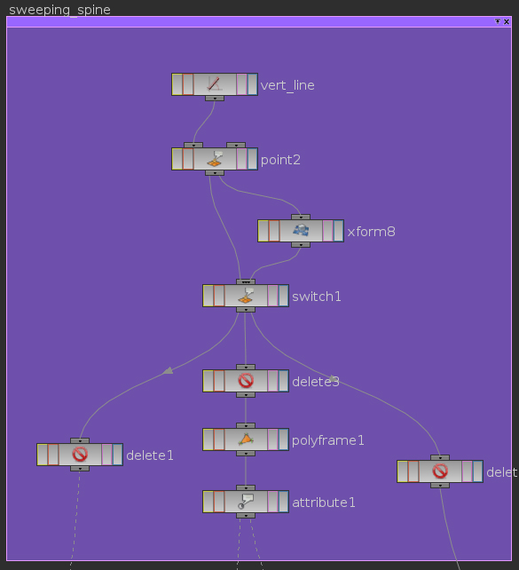
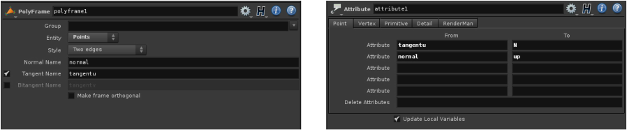
Placing the head was a difficult task. I tried to animate it on its own seperate sine wave to coincide with the motion of the body, but it would never quite line up. Instead I used a polyframe and attribute node on the line, to flip the normal with the tangent, and put this flipped normal into an attribute that I could then transfer to the head.
For the head, I again used a delete node from the line to delete all points except for the last one, then used attribute copy to give this point to normal of the line.
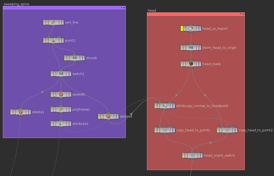
The next problem was how to elongate my line to connect with the back of the head. To do this, I used an add node to add an extra point on the end of my line, then obtained the normal information of the last point. This information is used to translate the newly created point to the next spot along the line.
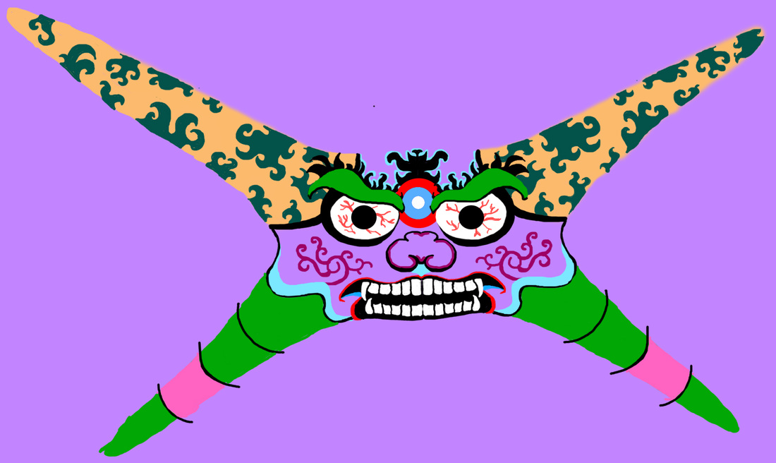
To texture the head, I exported the geometry as an OBJ to Roadkill, and unwrapped the UVs. I then exported the map to Photoshop so I could paint the mask.
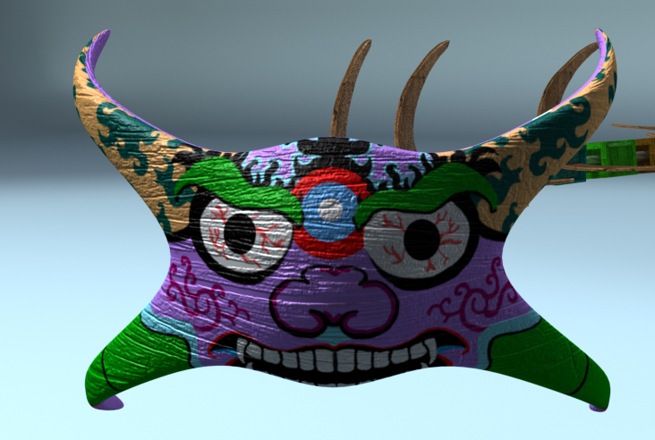
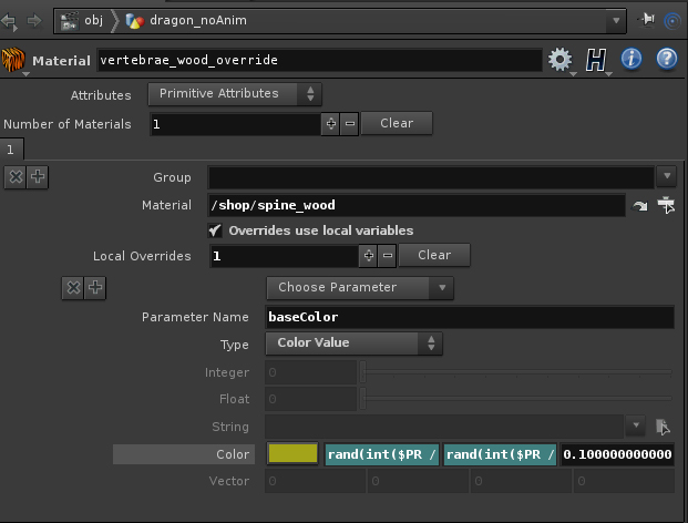
For the texturing the vertebrae and wings, I used a wood color map mixed with a base color. On the non-winged vertebrae, I used a material override to randomize the base color.

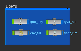
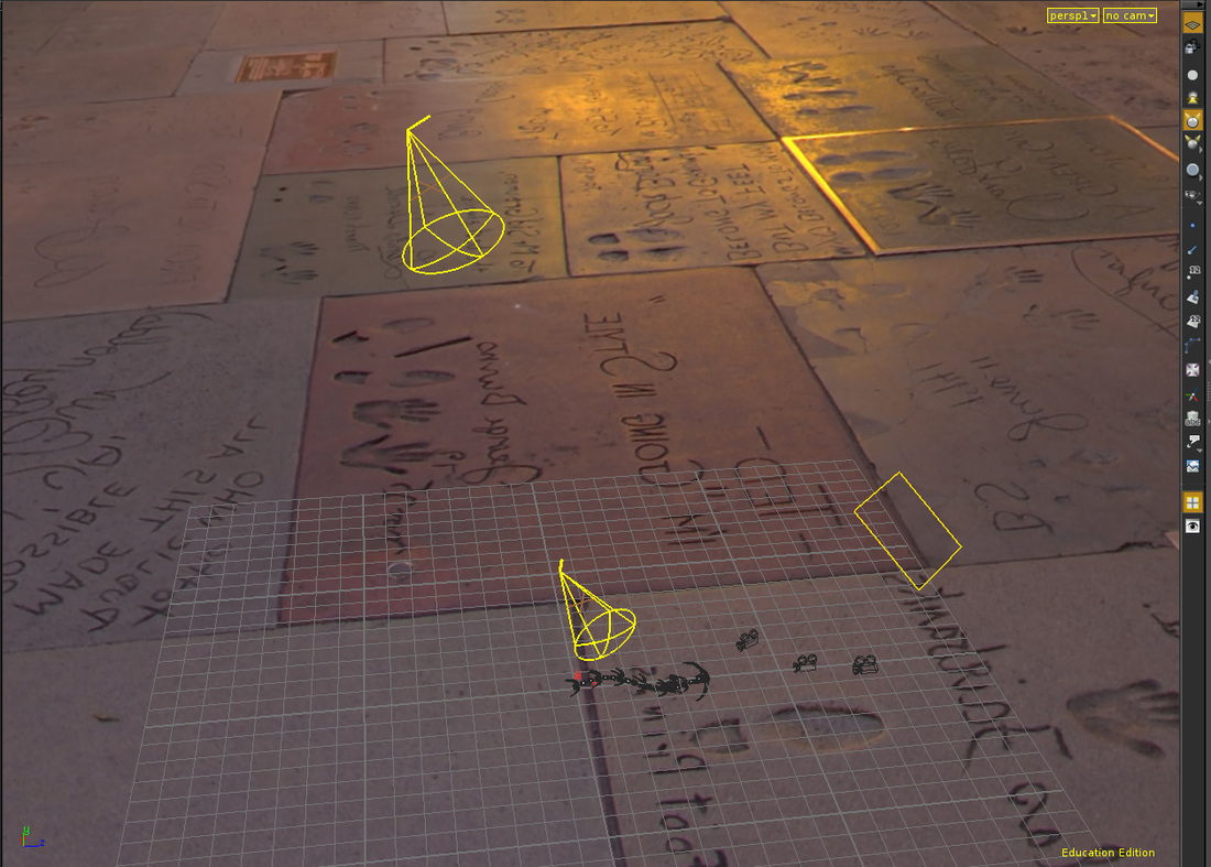
This project was challenging and a lot of fun. With the help of Professor Fowler, I tackled several tough problems, and I am very happy with my results. To further this project, I want to refine the shaders and experiment with different lighting setups.